28 Jun 2023 Dual PMAG wiring
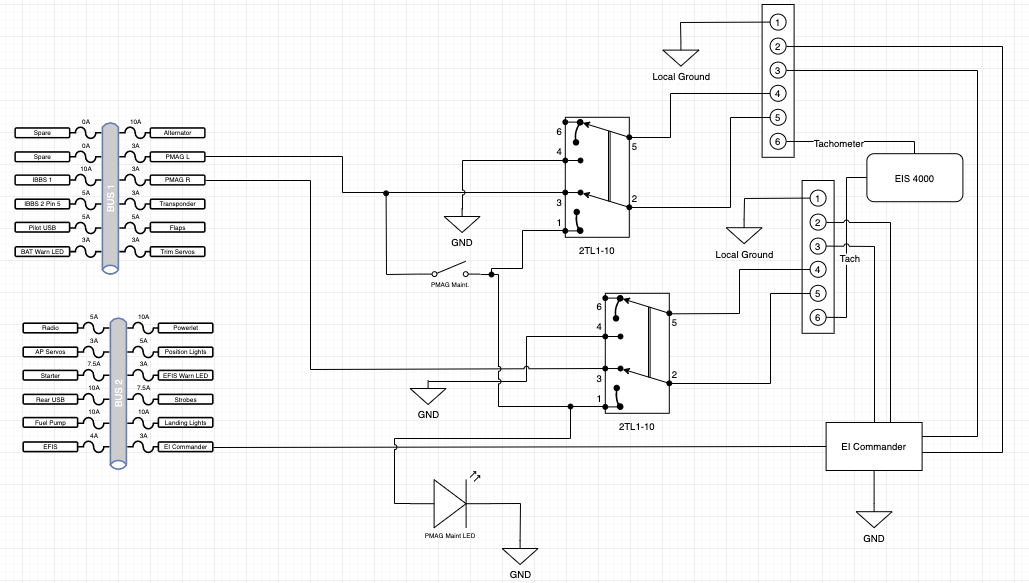
Frequently, discussion comes up about how to wire the PMAGs or which switches to use. I thought I would share my design and implementation.
I use 3 switches, wired like this diagram. They are Honeywell TL toggle switches, 2x model 2TL1-10 (ON-ON-ON), and 1x model 1TL1-3 (ON-ON). These very high quality Honeywell TL toggle switches are available at all fine electronic supply companies, like Steinair (https://www.steinair.com).
For the two 2TL1-10 switches, here is how they are operated:
Up is normal mode – PMAG “active” and 12v to PMAG
Middle is “PMAG internal generator test” mode, so the PMAG is active with no 12v power
Down is off – no power and PMAG is grounded (inactive)

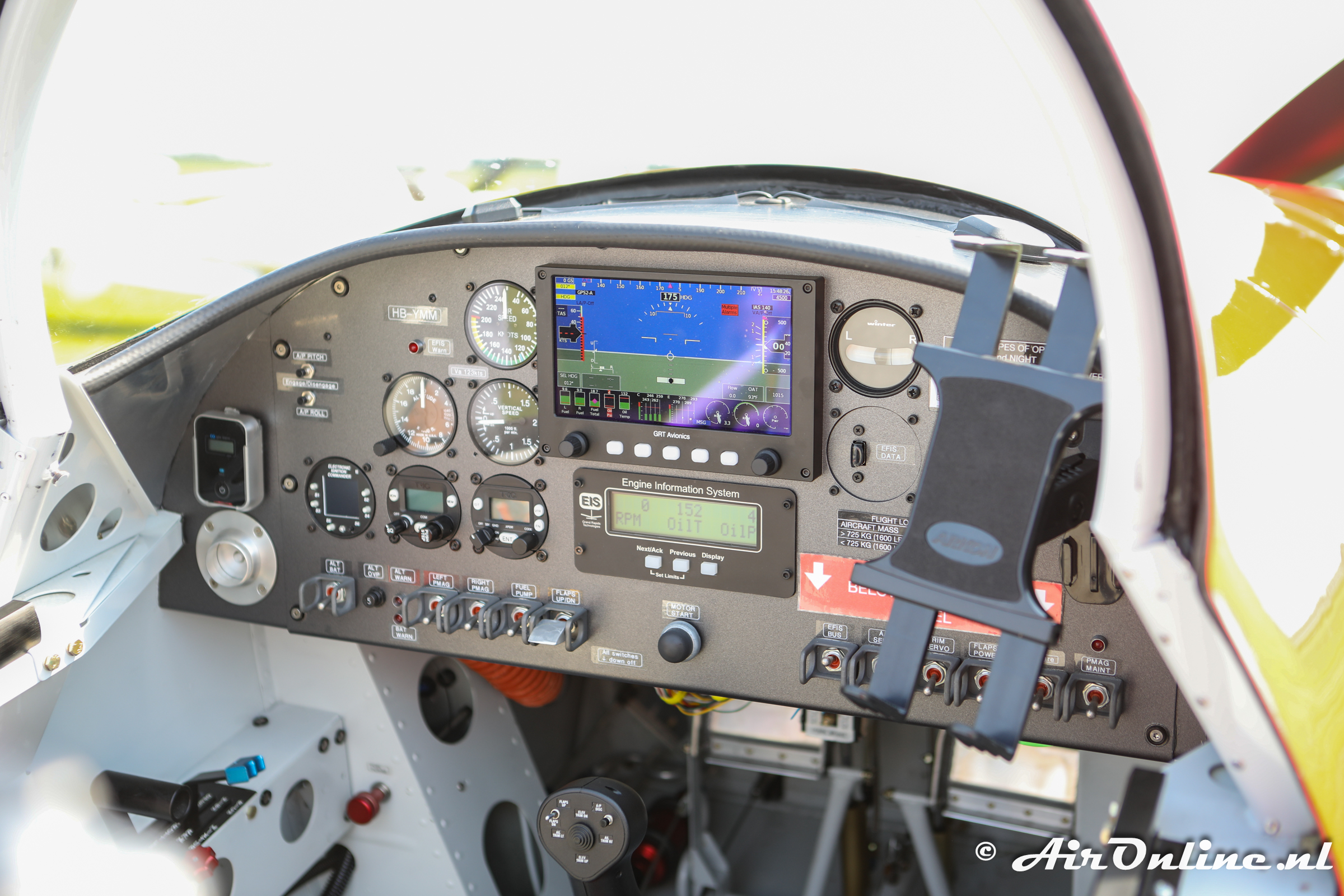
Below you can see the three switches – the two PMAG operating switches on the left, and the “maintenance” switch on the far right. That switch is only used when setting the PMAG timing.

I like this design because it’s easy to test the PMAG, the normal operating mode is “UP” like the other switches, and there is nothing unusual for any normal pilot to think about. Just put all switches up and fly. Of course, I have an exception – the Maintenance switch should only be up when doing PMAG maintenance (timing) but it won’t hurt if it’s up all the time.
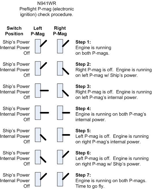
Here is an excellent diagram from Bill Repucci’s website: https://repucci.com/bill/electrical.html about how to test the dual PMAGs with a switch design as described above.


Sorry, the comment form is closed at this time.