05 Jun 2005 MT Propeller sensor and slip ring contacts bracket
Here is where I describe mounting the stationary contacts for the propellor sensor and control slip ring.
I ended up not using the angle and flat stock that was sent as the mounting system for the sensor. The angle was not quite long enough to provide enough edge distance for the bolts, and I felt better using angle instead of flat stock in order to provide a bit more lateral stability to the sensor.
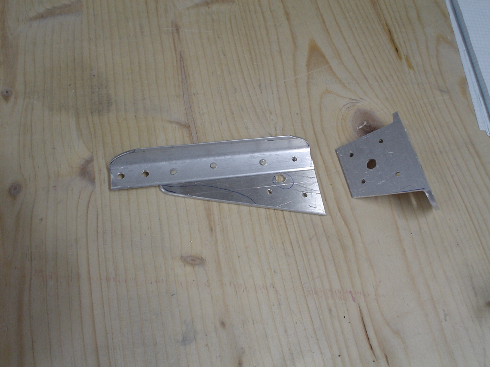
Here is a view of the pieces I fabricated. This is not high-tech stuff, you just have to measure, cut, drill, and rivet, just like the rest of the project.
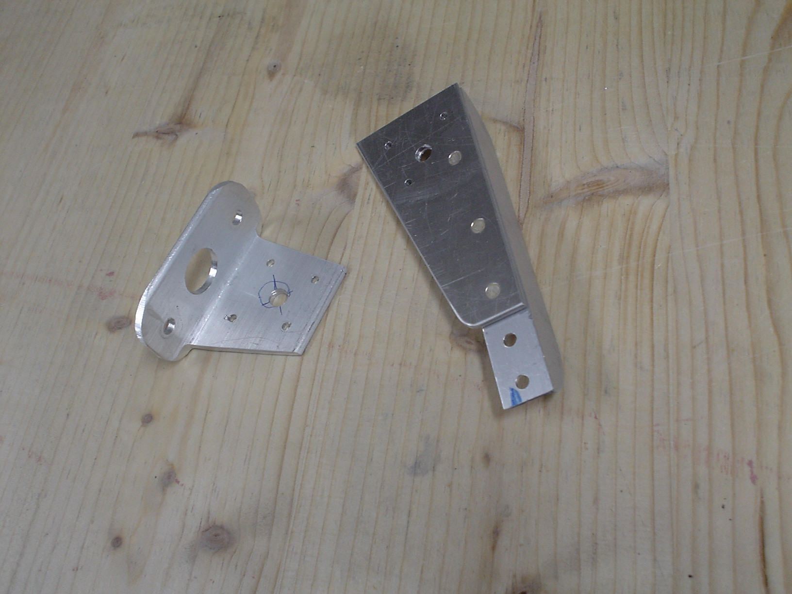
Pieces from a different angle.
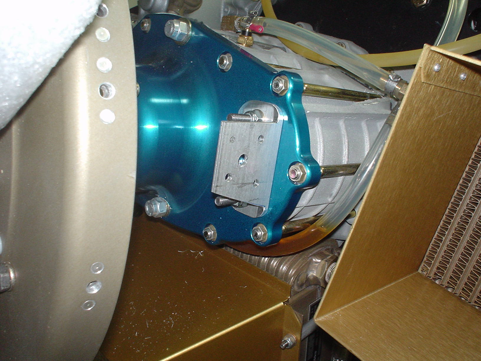
Here is the piece that mounts on the PSRU. There are studs already installed there, but I have to say I don’t really like the fact that the threads are very coarse. I would have prefered finer threads.
A view from the right side.
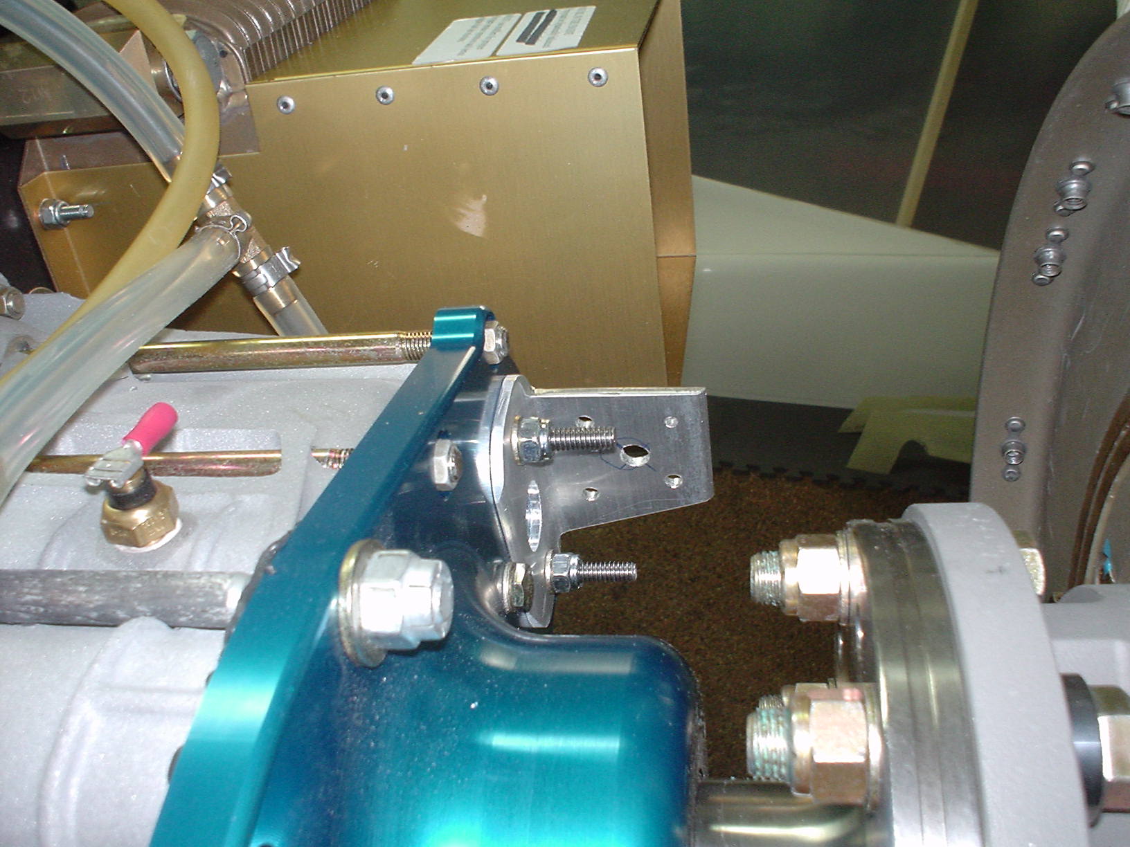
Mounting arm and sensor from the left side.
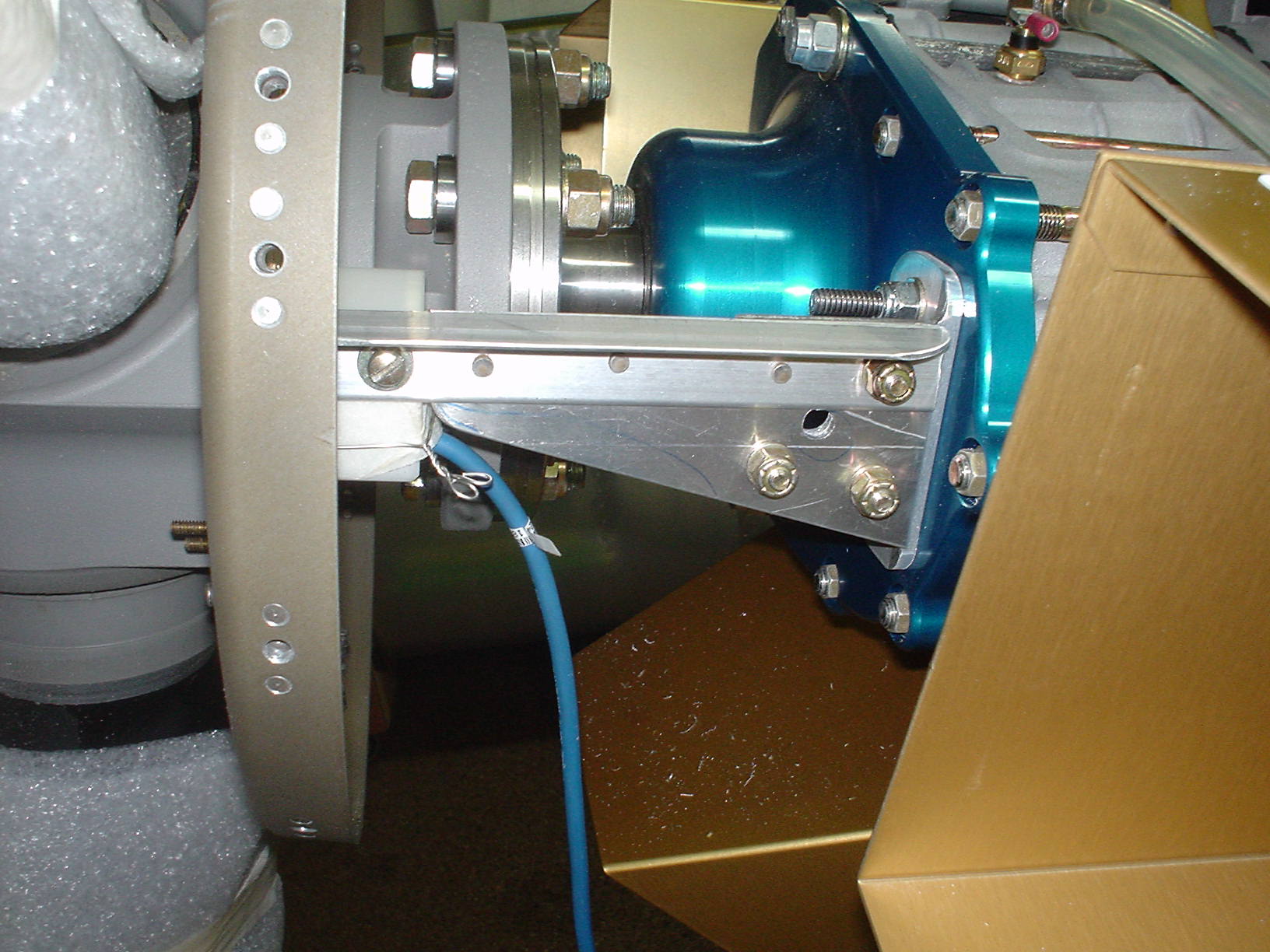
A view from the bottom.
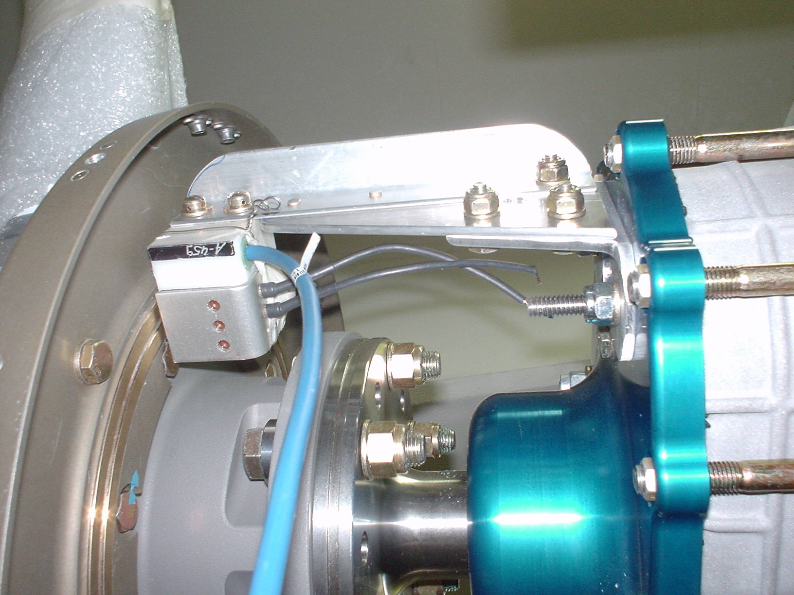
A view from the top.
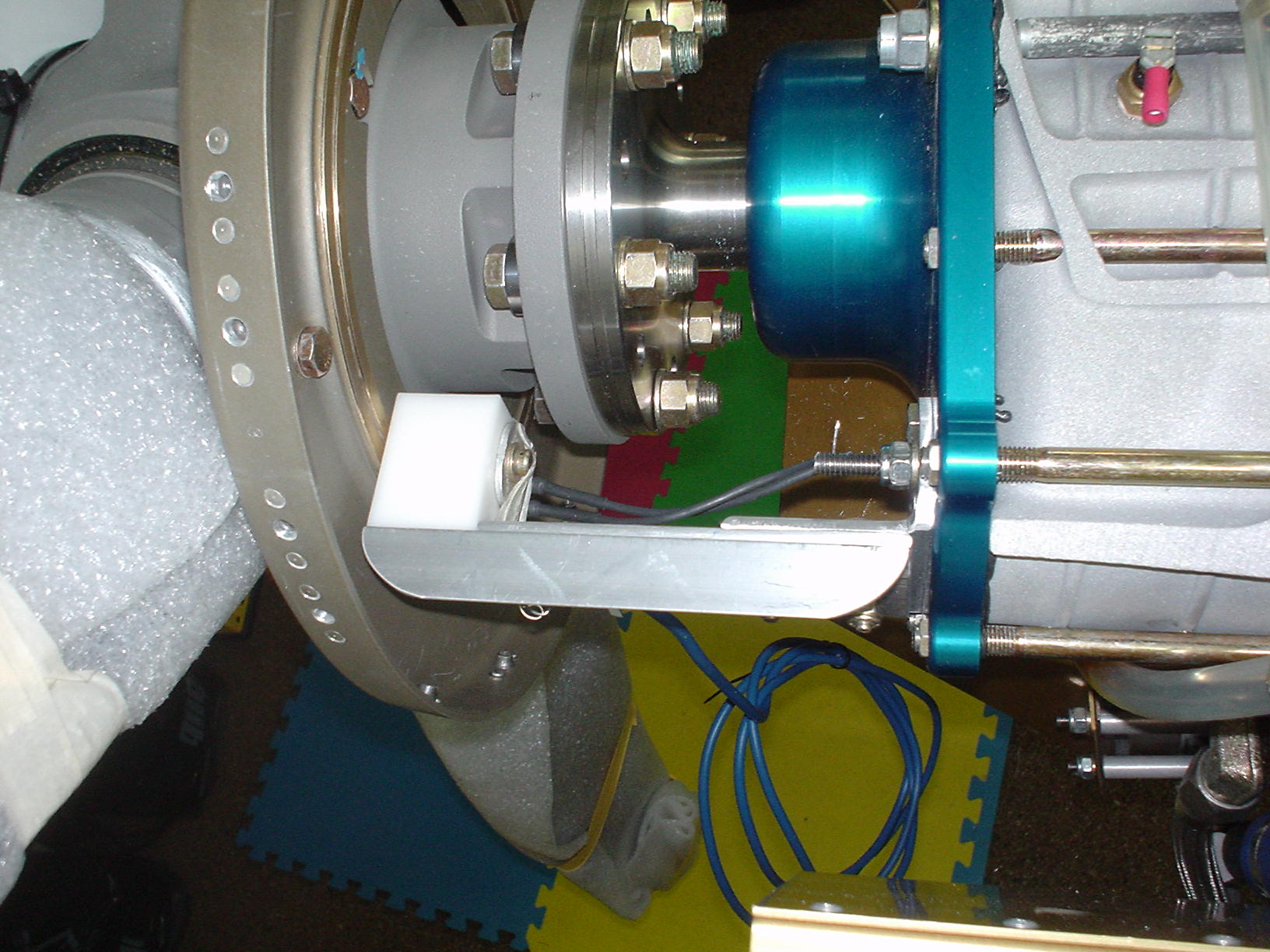
The MT installation manual says that the sensor should be between 0.8mm and 1.2mm from the prop hub. I used a piece of safety wire to hold the little slip blocks in, so that wire was my spacer. It was about 1mm thick, I think. It seems like it turned out ok. Now I need to anodize the bracket, or prime and paint it.
UPDATE: 2005-06-29
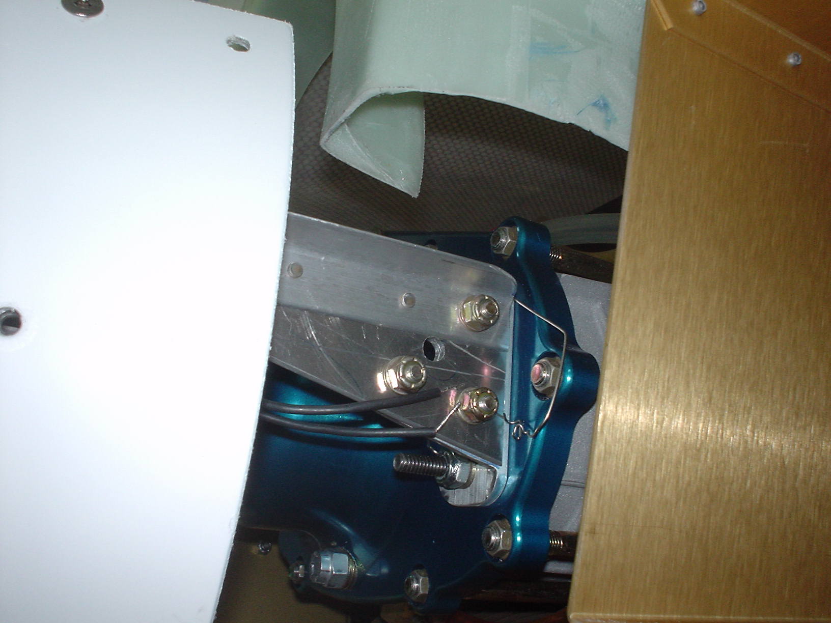
The bracket seems to get in the way of the top cowl. I think I will have to re-do the bracket, or cut the cowling. I think it will be easier to make a new bracket.

Sorry, the comment form is closed at this time.